QRP 40 meter CW transceiver
QRP 40 meter CW transceiverI finally got my act together and built a transceiver. It's for 40 meters CW and has about 4 watts output. Some of the details may be of interest to other homebrew experimenters.
Use the links below or over on the right to navigate through the article.
Introduction
IntroductionAbout six months ago I built a transmitter for 80 meters as my first homebrew project for many years. I had plenty of QSOs on the air with it using my old Kenwood TS430S as a receiver. That was fun but I really had the urge to operate homebrew for both TX and RX. I also wanted to keep things as simple as possible so, despite their limitations, I decided I'd try a simple direct conversion. I have fond memories of building and playing with a DC receiver back in the late 1970's using a LM1496 chip as a mixer. I decided it was time to move to 40 meters which is a great band for CW.
The transmitter consists of just the driver (Q2) and power amplifier (Q3) stages from the Universal QRP Transmitter by Wes Hayward, W7ZOI as described in QST April 2006. This article is freely downloadable from the ARRL even for non-members. I've found this to be a great design to use as a general purpose power amplifier. It's very simple and stable. I've built 80 meter and 40 meter versions now and both have "just worked" without any hassle at all. I'm using BD139 transistors for both Q2 and Q3 because the 2SC5739 is no longer available. See my previous post about my experience with this design on 80 meters.
For the receiver, I followed the very simple direct conversion design using an NE602 and LM386 as described in the first chapter of Experimental Methods in RF Design aka EMRFD by Wes Hayward, Rick Campbell KK7B and Bob Larkin, W7PUA. I later looked at Wes' Micromountaineer transceiver design from QST July 2000 and found the receiver to be pretty much identical. If you're an ARRL member you can download the original article from arrl.org but Wes also generously makes the schematic downloadable from his web site.
They are both driven by my DDS-60 and Arduino based VFO. The Arduino also provides timing for semi break-in keying and generates the audio sidetone. The software has been enhanced to provide the required shift and RIT functionality.
Most of what I had to figure out was around how to do the transmit / receive switching. For simplicity, I decided to stay with a mechanical relay and semi break-in (QSK) keying. Semi break-in is where it switches to transmit automatically on key down but stays on transmit for a time out period (in my case 750 ms) after the key is released. This means that it tends to stay permanently on transmit while you're sending. Full break-in is where the switching is fast enough so that the receiver comes back on between dits and dahs. That's more difficult to do properly and an unnecessary challenge for this project.
The CW keying is feed to an Arduino input. The Arduino implements the timeout delay and outputs a transmit / receive logic signal. Switching transistors take care of the voltage translation between the transceiver's 12 volt levels and the Arduino at 5 volts.
Some timing calculations were in order to ensure that we weren't going to clip the first CW element too much while we switch from receive to transmit. A rule of thumb is that one element time (i.e, one dit) in ms is 1200 / speed in wpm. 40 wpm means 30 ms dits. The slowest part is the relay. Other delays are probably insignificant in comparison. The datasheet for the relay I bought from Mouser says 7 ms switching time. So, if you're sending at 40 wpm, the first 30 ms dit is somewhat clipped. I doubt that I ever send above about 20 wpm so I feel comfortable with it and the signal sounds good. If you're into high speed CW then you might have to do something different such as the method used in the Micromountaineer which does not use a relay.
The relay is DPDT. i.e., it has two sets of contacts. One is used for the antenna. I decided to use the other contacts to prevent the RF drive coming on until the relay has switched and we can be sure that the antenna is connected to the transmitter. I don't know if this is really necessary but it seems like a simple way to avoid that few ms which would occur when the transmitter is keyed on with no load before the relay has switched.
I've taken the receiver muting and sidetone injection straight from the Micromountaineer except that I didn't bother with the MOSFET switch in front of the NE602. That seemed unnecessarily since I'm switching the antenna with the relay so the receiver is disconnected during transmit. I am however using the two MOSFETS to block any noise from the NE602 during transmit. The sidetone comes from the Arduino as a 5 volt square wave so it needs to be well attenuated before being fed to the LM386. I used a trimpot to adjust the sidetone volume. It sounds fine to me but if you prefer something closer to a clean sine wave then I'm sure a better low pass audio filter could be designed.
Schematic and components
Schematic and componentsThe schematic is shown below but you can also click here to download a PDF.
You really need to read the introduction first for this to make sense.
It's several separate diagram segments showing the pieces that I put together. Where component names appear (Q4, R11 etc) these refer to those on the Universal QRP Transmitter schematic.
I haven't shown all the bypass capacitors. Liberal use of 0.1 uF capacitors on the DC lines is recommended.
Some of the component values were governed by what I had in the junk box rather than any exact calculations. 10K resistors setting the base current of the switching transistors seem to work well but the value is probably not critical so long as the transistor is saturated.
Those components that I didn't have in the junk box came from Mouser.
Don't forget that the NE602 needs 5 volts. I used a three terminal regulator. I run the LM386 from 12 volts as does the Micromountaineer although the EMRFD circuit powers it from 5 volts.
You might not be able to buy an NE602. Luckily, the NE612 and SA612 are available and, for our purposes, are the same thing. See this post where Bill N2CQR of SolderSmoke podcast fame publishes a post from Paul NA5N with the whole story of this chip.
You might not be able to get an LM386 either. I used an equivalent from Mouser called a NJM386BD.
The EMRFD receiver design has slightly different component values for the tuned circuit at the receiver front end than the Micromountaineer 40 meter values here. The EMRFD design specifies the inductor as 20 turns of #26 wire on a T37-6 toroid. The trimmer is a 180 pf and the capacitor across it is 270pf. The exact combination is probably not critical but obviously the important thing is that it must resonate at the received frequency. Trimmer capacitors seem to be difficult to get these days. I used a 120pf trimmer from Mouser which is the biggest capacitance they stock. One setting easily covers the 40 meter band so a trimmer is fine for this. It doesn't need to be a front panel control.
If you use the typical type of trimmer capacitor which turns around and around, make sure the receiver noise peaks in two places. It's easy to be fooled and think it's peaking when it's really just getting closer to resonance when it's at maximum or minimum capacitance. If it's truly resonating then you should be able to turn the trimmer so that the other side of the movable plates are meshed with the same result. You may need to fiddle with the fixed capacitor value or the number turns on the coil if it's not resonating.
Since I didn't really know what was required, I used a trimpot to set the level of oscillator injection to the NE602. The level does not seem to be critical. I don't have anything equivalent to the 51 ohm resistor, r23 in the Micromountaineer circuit. I have nothing on the NE602 pin 6 except for the 3300pf (random value from the junk box) coupling capacitor.
The Micromountaineer design has its RF gain control / attenuator in what looks to me to be a unusual configuration. I have my RF gain control in the more typical voltage divider configuration as does the EMRFD design.
Software and operating instructions
Software and operating instructionsI'm assuming you've read my article describing the Arduino controlled DDS-60.
Click here to download the Arduino software. It now has a "Transceiver mode" which is selected between normal mode and QRSS when pressing button 1. You'll know when it's in transceiver mode because RX will appear in the top right corner of the display.
Transceiver mode implements the transmit / receive switching, audio sidetone, frequency shift and RIT (receive incremental tuning).
The two settings that you might want to change are:
CW_FREQ. This is the CW audio frequency in Hz. I like it to be about 800 Hz but it's a personal preference. This sets both the audio sidetone and, more importantly, the DDS frequency shift that occurs between transmit and receive.
TR_TIMEOUT. This is the transmit / receive timeout in ms. i.e, how long the key has to be up before we switch back to receive. The best value depends on your sending speed but I've found that 750 ms works well for me.
At first I wondered if I might need to use interrupt processing for the CW signal but this wasn't required. Polling in the main loop is easily fast enough. The loop executes in microseconds when the tuning encoder is not being turned.
Operating Instructions
Set to transceiver mode by pressing button 1.
On receive, the DDS frequency is CW_FREQ (e.g, 800 Hz) higher than what the display shows. Therefore, if you tune to the high side of a received CW signal so that the audio tone is CW_FREQ then the display will show the transmitted frequency. It is important that you tune to the high side if you intend to reply to the station, i.e, if you can turn the tuning knob so that the displayed frequency increases and the pitch of the received CW audio gets higher then you're on the correct side. I chose this side because it kind of feels more natural to me and it's the same side that you would use to resolve LSB phone signals further up the 40 meter band. Be careful at the band edges. You could end up transmitting outside the band if you tune to the wrong side.
On transmit, the DDS frequency and therefore your transmit frequency is exactly what is shown on the display.
Button 2 toggles the RIT on and off. The offset in Hz appears in the lower left of the display. The frequency step for the RIT is selected with button 3 in the usual way but the value is maintained separately for the RIT and the main tuning. Changing one won't change the other. I prefer to have the RIT at 10 Hz per step while the main tuning is usually at 100 Hz or higher.
That's about it. There are room for improvements as I will talk about later.
Photos
Photos
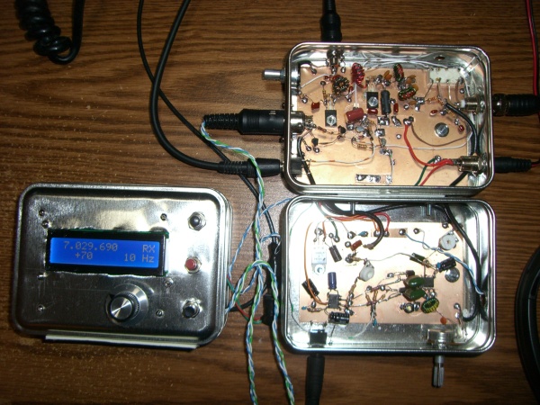
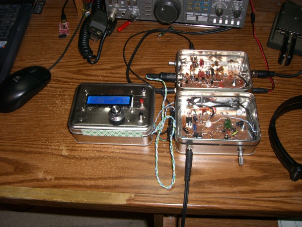
As usual the mechanical side of things is my greatest challenge. That's the receiver in front and transmitter at the back with the DDS VFO beside it. It's built ugly / manhattan style in small metal boxes available from the craft chain store called Michaels. I had initial thoughts of building it in three completely separate boxes for plug and play flexibility but the interconnections got too complicated for me. The transmitter and receiver boxes are screwed together as one unit.
I used an audio style DIN plug for the connection between the DDS and transceiver. The RF is a separate RG174 coax cable into an RCA connector on the back.
The DDS display indicates that the RIT is on with a +70 Hz shift.
Final thoughts
Final thoughts
I'm having lots of fun operating this transceiver. I've worked around North America and even worked a few Europeans. I find it very satisfying to communicate using simple homebrew equipment. I hope it doesn't sound elitist but it definitely has a feel of "real" ham radio about it. The diverse combination of old and new is fun to think about. By that I mean the sophisticated DDS, microprocessor controller, simple direct conversion receiver and of course the ancient thing that makes such simple equipment usable, CW morse code.  I usually send with a K1EL WinKeyer.
I'm sure there's a good chance that if had bought a kit rather than going with the all homebrew approach then I would have spent less time, money and ended up with a much more robust and attractive final result but ... I just wanted to do my own thing. There are some great inexpensive kits available in the QRP community and I encourage anyone to take that route if it feels like the right way to go.
40 meters is a great band for CW. There are the DXers at the bottom of the band, the QRPers up around 7030 and 7040 and then there is another group up around 7110. I think that last group is or at least used to be called the technicians' segment even though US technician class licensees can use 7025 to 7125. Slow CW seems to be the norm up at 7110 so it's a good place for anyone wanting to practice.
The performance of the receiver has exceeded my expectations. I get absolutely no "tunable hum" or other typical direct conversion issues with it. I'm lucky in that I don't have any strong local AM broadcast stations. I thought some shortwave broadcasts may have been a problem with the simple single tuned circuit in the front end. There are some very strong signals in the 31 meter band just below 10 MHz but they don't seem to cause me any problems. Your experience may vary. You might need to improve the front end selectivity if you have strong local signals. A parallel tuned circuit in series with or a series circuit across the input could be used to null out a troublesome local broadcaster if there is one particular station causing problems.
The receiver could probably do with an audio gain control. For most signals, I have the RF gain / attenuator barely above zero to avoid excessive volume in the headphones. At times I think it would be nice to turn the AF gain down and crank the RF gain up a bit. I've heard mention of the TDA7052 audio amplifier chip as a good alternative to the LM386. I think its gain can be controlled by a DC voltage level which sounds like a nice simple way to do it.
At times an audio filter would be nice but I haven't really had a problem with the lack of selectivity. As I get older I guess my ears' high frequency response is fading so I already have at least a low pass filter built-in Of course the beauty of a direct conversion is its simplicity. If you try to improve it with lots of enhancements then there probably comes a point when it makes sense to give up on direct conversion and build a superhet with a IF narrow enough to give "proper" single sided reception.
There is definitely room for improvement with the user interface. The most immediate issue is that we need more buttons. I'm thinking of building a new version of the DDS box. I would use a shift register to drive the display as a serial device. That would free up enough pins to have nine buttons in a 3x3 matrix. The extra buttons would allow such enhancements as:
- Easy switching back and forward between 100 Hz to 10 Hz steps. Cycling through all the steps to get from 10 Hz back to 100 Hz is a little tedious.
- A "reverse shift" mode which allows tuning to the low side of a signal to avoid QRM but still transmit on the correct frequency. I can do this now with the RIT by tuning all the way down through zero beat and up the other side but an instant switch would be nice.
I'm sure there are other enhancements but I'm not sure when I'll get to this next step. For now I'm going to get on the air and enjoy some operating.
73
Ross
40m CW project
Ross
Great website, well done.
It's amazing how things run in parallel, miles apart. I have also been messing with simple CW transmitters and rediscovered the BD139. I have 2 of them in my version of the Universal MkII, one in a Twofer, and one in the original 'Little Joe' Universal tx. As you say, they are good value replacements.
I have pushed the Twofer up to 20m and it performs just as well as on 40m.
My BD139s have 'live' back plates wired to the collector, I see yours are bolted to the PCB. Interesting!
I have just aquired a DDS from G-QRP Club, a Kanga US module, I think, and have been looking at a MicroMountaineer style trx. Great minds think alike!
Keep up the good work Ross and maybe see you on the air over Christmas/New Year when I get a bit more time to operate.
73, Steve, G0FUW
Thanks Steve. Great stuff. I
Thanks Steve. Great stuff. I was a little unsure if the BD139s were really insulated. The back is plastic but it has a somewhat shiny metallic look to it. I tried hard to scratch one as a test but couldn't get any sign conductivity with the collector so I think they are well insulated. A mica washer is probably a wise idea anyway just in case. Do yours have an obvious metal back? Mine are BD139STU if that means anything.
73
Ross
Ross Mine have a metal plate
Ross
Mine have a metal plate on the back linked to the centre pin, and I have 3 different brands, all much the same, although some are grey in colour, others black. One of our smaller suppliers was offering 10 for £3, about $2, in SPRAT so I stocked up!
73, Steve, G0FUW
Please, completed al schematic
Great Work man!
Please, please, I do not understand all in various schematics...
Post please any complete schema diagram of interconnection between DDS, RX, TX with all materials (transistors, resistors, capacitors....).
I see only: http://www.theladderline.com/sites/default/files/ross/qrp/qrp-40m-cw.gif
But I do not exactly where connect to TX, RX,...
This will help very well.
I am sorry for my bad english.
Best regards and thank You,
Daniel :)
Czech Republic
Hi Daniel Thanks for your
Hi Daniel
Thanks for your comment. I can't really publish the transmitter and receiver design here because they are not my work.
You need to study the transmitter which is the Q2 and Q3 stages of this:
http://www.arrl.org/files/file/Technology/tis/info/pdf/0604028.pdf
And the receiver which is just the receiver part of this: http://w7zoi.net/mtnr4.pdf
Then look at my schematic and my earlier post about the DDS-60.
73
Ross